Developer Tools2025

Enteronova Controller

A web-based BLE testing console built for Enteronova's IBS/IBD neuromodulation device. One screen to replace five tools — from device connection through oscilloscope testing to exportable reports.

Unified testing workflowBuilt-in test reportsBLE + scope integration
Web BluetoothMedical DeviceFirmware TestingHardware
Enteronova Controller — BLE connection, mode toggle, and treatment controls

TL;DR

Built a single-page web app that replaced a fragmented firmware testing workflow — BLE connection, real-time ADC readback, oscilloscope waveform guides, and exportable test reports — so engineers could test medical hardware from one screen instead of five tools.

Overview

Role

Design Technologist

Company

Enteronova

Stack

HTML/CSS/JS, Web Bluetooth API, BLE NUS

The Problem

Five tools, zero flow

Testing firmware on a medical neuromodulation device was a fragmented mess. Engineers had to flash firmware via J-Link, connect BLE through nRF Connect, run RTT logs from the command line, set up an oscilloscope with the right probes and settings, then manually note readings on paper. Each context switch broke concentration, and reproducing a bug meant reassembling this entire toolchain from scratch.

RTT via CMD

In-app device log with filters

nRF Connect for BLE

One-click BLE connect

Manual probe setup

Guided scope setup + ASCII wiring diagrams

Pen & paper results

Structured test report with export

Key Insights

01

The biggest time sink wasn't any single tool — it was the constant switching between them. A unified interface would collapse 5 context switches into zero.

02

Firmware engineers don't need a pretty GUI — they need raw control with guardrails. Simple mode for routine tests, raw mode for deep hardware debugging.

03

Oscilloscope testing was the most error-prone step because probe wiring and settings changed per test. Embedding expected waveforms and setup guides directly in the tool eliminates guesswork.

The Solution

One webapp. Full hardware control.

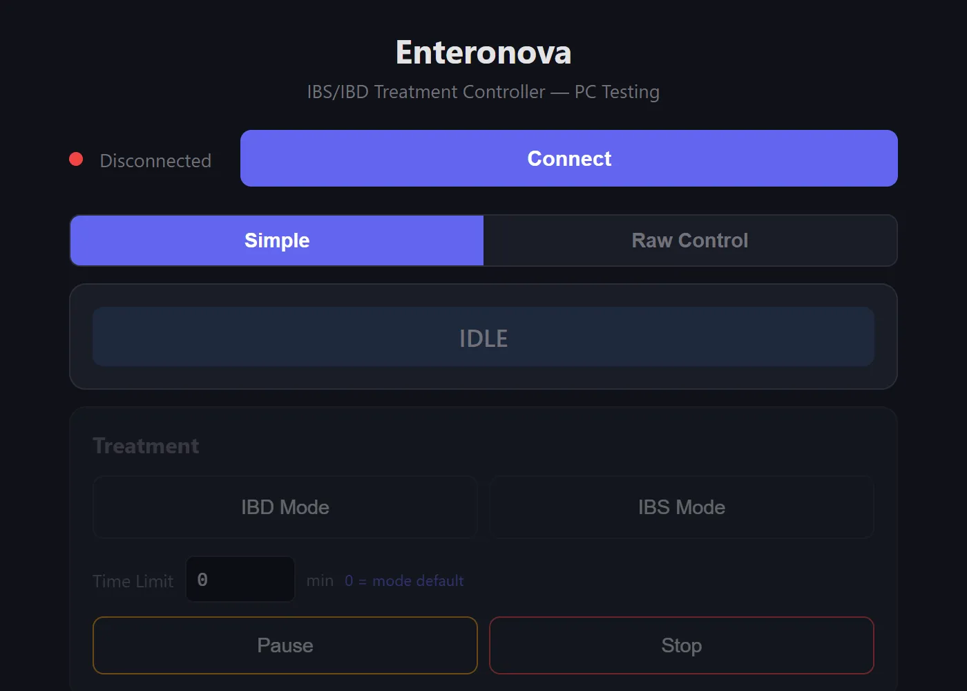
A single-file HTML webapp that connects to the device over BLE and provides everything a firmware engineer needs: treatment controls, raw hardware register access, live ADC readback, oscilloscope waveform guides, and a structured test report builder — all from a browser tab.

Simple Mode

IBD/IBS treatment selection, amplitude sliders, pause/stop — for routine testing

Raw Mode

Direct PWM control, DPOT registers, channel enable, waveform generator — for hardware debugging

Simple Mode — treatment selection, amplitude sliders, pause/stop controls

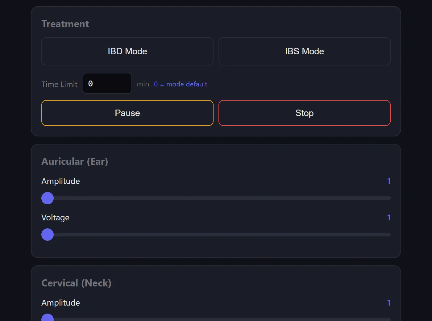
Simple Mode — treatment controls for routine testing

Raw Mode — PWM control, voltage levels, bridge duty cycle

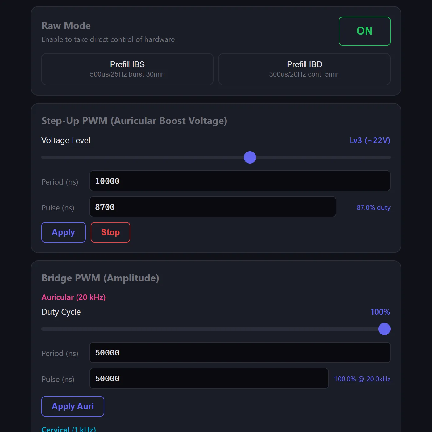
Raw Mode — direct hardware register access

Architecture

Single file, zero install

The entire tool is a single HTML file — no build step, no dependencies, no server. Engineers open it in Chrome, click Connect, and they're testing. The Web Bluetooth API handles device communication over BLE using Nordic's UART Service (NUS), with a custom structured command protocol for reliable two-way control.

BLE Protocol

Commands use a #-prefixed format (#M1 = enter raw mode, #UA = step-up ack). Responses are parsed by type — mode acks, ADC telemetry (#R0,auriBus,cervBus,auriOut,cervOut), 15-field parameter queries (#Q...), and error codes (#ERR,reason).

State Machine

Tracks device state (IDLE → RUNNING → PAUSED) with a RAW mode overlay. UI cards enable/disable based on connection + mode. Auto-starts ADC telemetry on connect, cleans up on disconnect.

Log Parser

Incoming BLE data is buffered and split on newlines. Each line is classified as a structured response (#-prefix), NUS protocol (value,unit pairs), or Zephyr kernel log — then routed to the appropriate handler.

Zero Dependencies

Pure HTML/CSS/JS. No React, no build tools, no npm. The ~2,500 line single file runs directly from the filesystem — critical for a tool that needs to work on any engineer's machine without setup.

Treatment Parameters

ParameterIBS ModeIBD Mode
Phase duration500 µs300 µs
Rest period~39 ms~49.4 ms
Frequency~25 Hz~20 Hz
PatternBurst (50 pulses, 3s pause)Continuous
Peak voltage (Lv3)±22V across 550Ω±22V across 550Ω
Peak current±40 mA±40 mA
Default duration30 min5 min

Features

Built for the bench

BLE Connection

Web Bluetooth API with Nordic UART Service (NUS). One-click connect, auto-reconnect, connection state management.

Treatment Controls

IBD/IBS mode selection with configurable duration, amplitude sliders for auricular and cervical channels, DPOT fine adjustment.

ADC Live Readback

Real-time telemetry at configurable intervals (200ms–2s). Auricular bus, cervical bus, and output voltage — cross-checked against scope readings.

Raw Hardware Mode

Step-up PWM control, H-bridge duty cycle, digital potentiometer registers, channel enable/disable, and a full waveform generator with phase, rest, burst, and duration parameters.

Device Log

Structured log viewer with level filters (DBG/INF/WRN/ERR) and 12 firmware module filters — stim, dpot, power, battery, treatment, BLE, stepup, led, buzzer, haptic, button, feedback — each color-coded. Includes text search, pause, msg/s rate counter, and log export.

Quick Presets

One-click IBS defaults, IBD defaults, max output, and safe state — plus parameter query to read live values from the device.

ADC Live Readback — 4-channel telemetry with configurable intervals

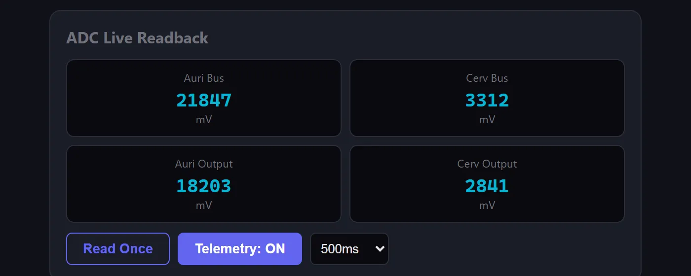
ADC Live Readback — real-time 4-channel telemetry

Device Log — color-coded log viewer with level and module filters

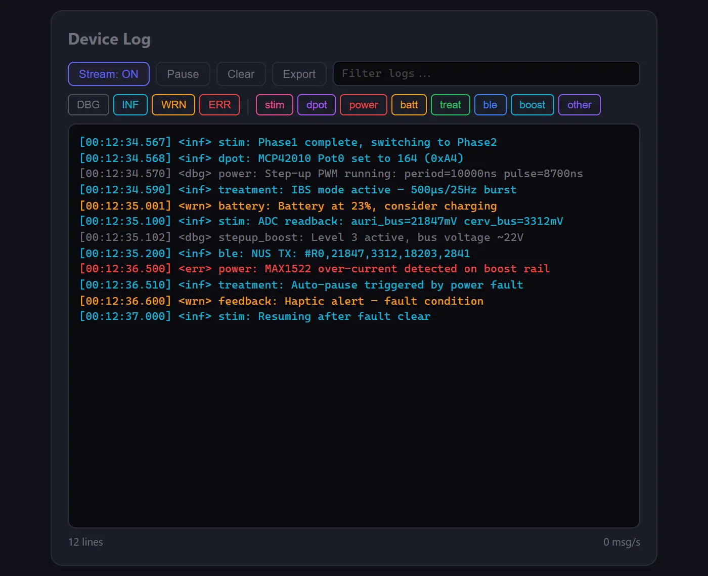
Device Log — color-coded with module filters

Scope Tools

Oscilloscope testing, built in

Instead of referencing separate documentation, the tool embeds everything needed for oscilloscope verification: ASCII wiring diagrams, per-test scope settings (V/div, timebase, trigger mode), expected waveform shapes, and automated sweep tests.

Single Pulse

Fire one biphasic cycle then stop. Set scope to single/normal trigger for a clean capture of the full +22V / −22V waveform.

Frequency Sweep

Auto-step through configurable Hz range (e.g. 5–50 Hz in 5 Hz steps) with a dwell time at each point. ADC values captured automatically.

Voltage Sweep

Step through all 6 step-up levels (Lv0 ~18V → Lv5 ~24V) with optional waveform running. ADC logged at each level.

Amplitude Sweep

Ramp H-bridge duty cycle from 0–100% in configurable steps. Measures actual output amplitude vs duty at each point.

Biphasic waveform across 550Ω load (CH1 − CH2 Math)

    Phase1       Phase2        Rest (~39ms)

+22V ── ┌──────┐                                ┌──────┐
        │500µs │                                │500µs │
  0V ───┘      └──────┐──────── ··· ────────────┘      └──────┐
               │500µs │     0V                         │500µs │
-22V ──        └──────┘                                └──────┘

        Full biphasic: +22V, −22V, rest
        Peak current: 22V / 550Ω = 40mA

IBS burst pattern (1s/div timebase)

 ┌─ 50 pulses (~2s) ─┐              ┌─ 50 pulses (~2s) ─┐
 │||||||||||||||||||||| │              │||||||||||||||||||||| │
 │                     │── 3s pause ──│                     │
 └─────────────────────┘              └─────────────────────┘
Oscilloscope Tools — single pulse, frequency sweep, voltage sweep, amplitude sweep

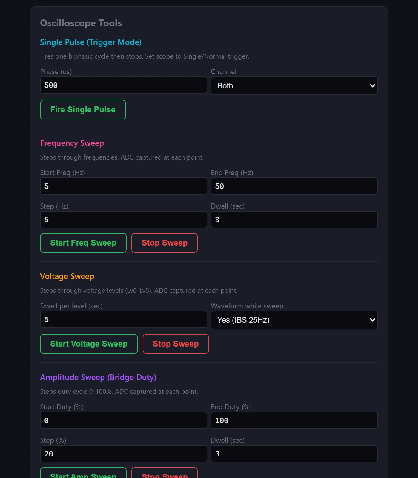
Oscilloscope sweep tools with progress tracking

Expected Waveforms — ASCII waveform diagrams and measurement tables

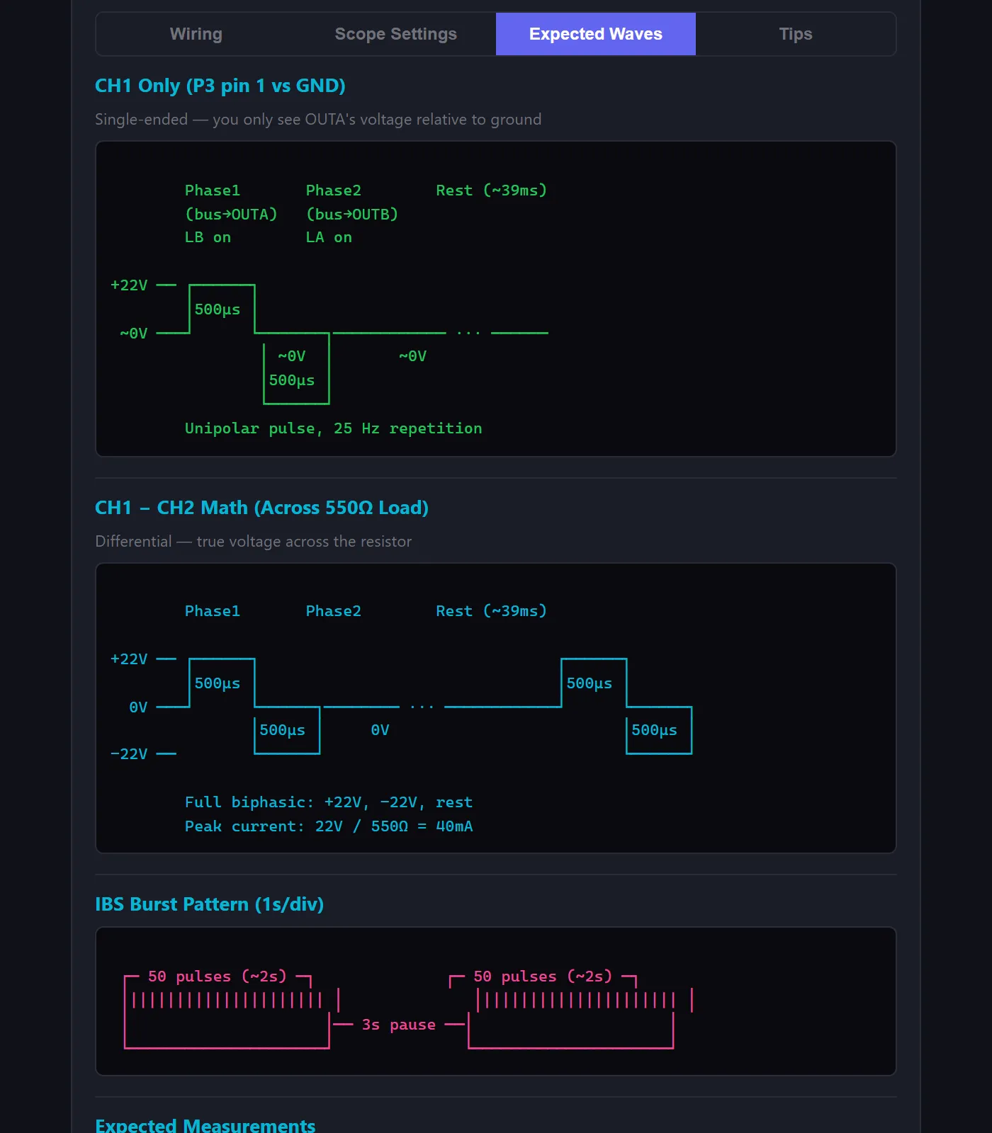
Expected waveforms with measurement reference

Setup Guide

No more flipping to the docs

Oscilloscope setup was the most error-prone part of testing — wrong probe settings, wrong ground connections, wrong V/div. So I embedded a full tabbed setup guide directly in the tool: wiring diagrams, per-test scope settings, expected waveforms, and a troubleshooting table. Everything the tester needs without leaving the page.

Probe Wiring (Auricular Channel)

P3 (Auricular Electrode Connector)
Pin 1 (OUTA) ──── 550Ω R ──── Pin 2 (OUTB)
     │                              │
   CH1 probe tip              CH2 probe tip

CH1 GND clip ──┬── PCB GND pad
CH2 GND clip ──┘

Both GND clips must connect to the same ground point — the scope shares ground internally. Different ground points will short-circuit through the scope.

Per-Test Scope Settings

TestV/divTime/divTrigger
Single pulse10V/div200µs/divCH1 rising, Single
Full cycle10V/div10ms/divCH1 rising, Auto
IBS burst envelope10V/div1s/divCH1 rising, Normal
Step-up PWM1V/div2µs/divCH1 rising, Auto
Bus voltage (DC)5V/div10ms/divCH1 rising, Auto

Built-In Troubleshooting

Flat line / no signal

Check probe connections, press AUTO, verify treatment is running

Readings are 10x off

Probe switch (1X/10X) doesn’t match scope channel setting

Only see one polarity

Looking at CH1 or CH2 alone — use Math CH1−CH2 for biphasic

Bus voltage stuck at ~3.8V

MAX1522 fault-latched — power cycle device (no J-Link connected)

Oscilloscope Setup Guide — tabbed wiring diagrams, scope settings, and tips

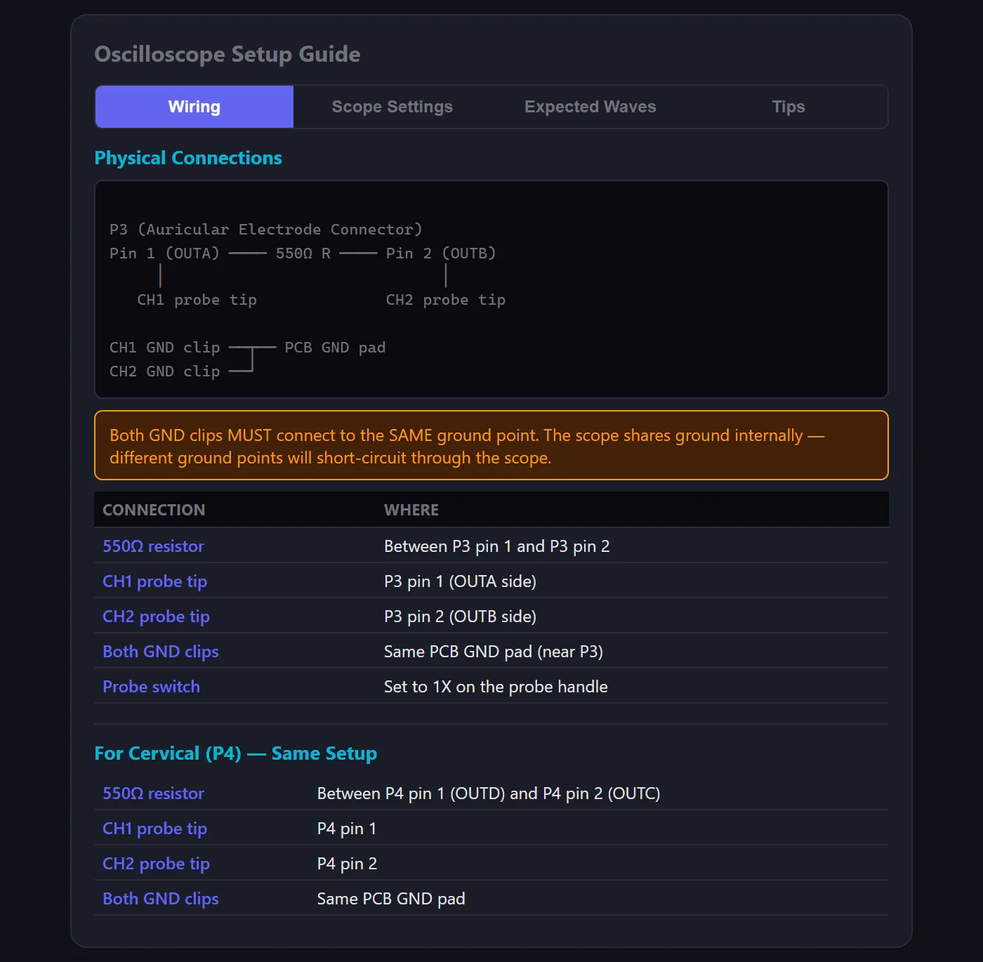
Embedded setup guide with wiring, settings, waveforms, and troubleshooting tabs

Reporting

Structured test reports

The tool includes a full test report builder with pre-loaded test suites, expected vs. measured comparisons, pass/fail/skip tracking, and one-click export to Markdown or PDF. Testers see expected values inline while testing — no more flipping between a spec document and their readings.

Each report captures device serial number, firmware version, oscilloscope model, load resistance, tester name, and environmental notes — so every export is a complete, traceable test record.

Pre-loaded Test Suites

Basic (key voltage checks) and full (all test points with expected values per IBS/IBD spec) — no manual entry needed

Live ADC Capture

One-click capture button reads the device’s 4-channel ADC (auri bus, cerv bus, auri output, cerv output) and auto-fills the measured column

Pass/Fail Summary

Real-time totals — total tests, pass, fail, skip — updated as the tester works through the table

Export to MD/PDF

Download structured reports with device serial, firmware version, scope model, load resistance, tester name, and all results

Test Report — pre-loaded test suites with pass/fail tracking and export

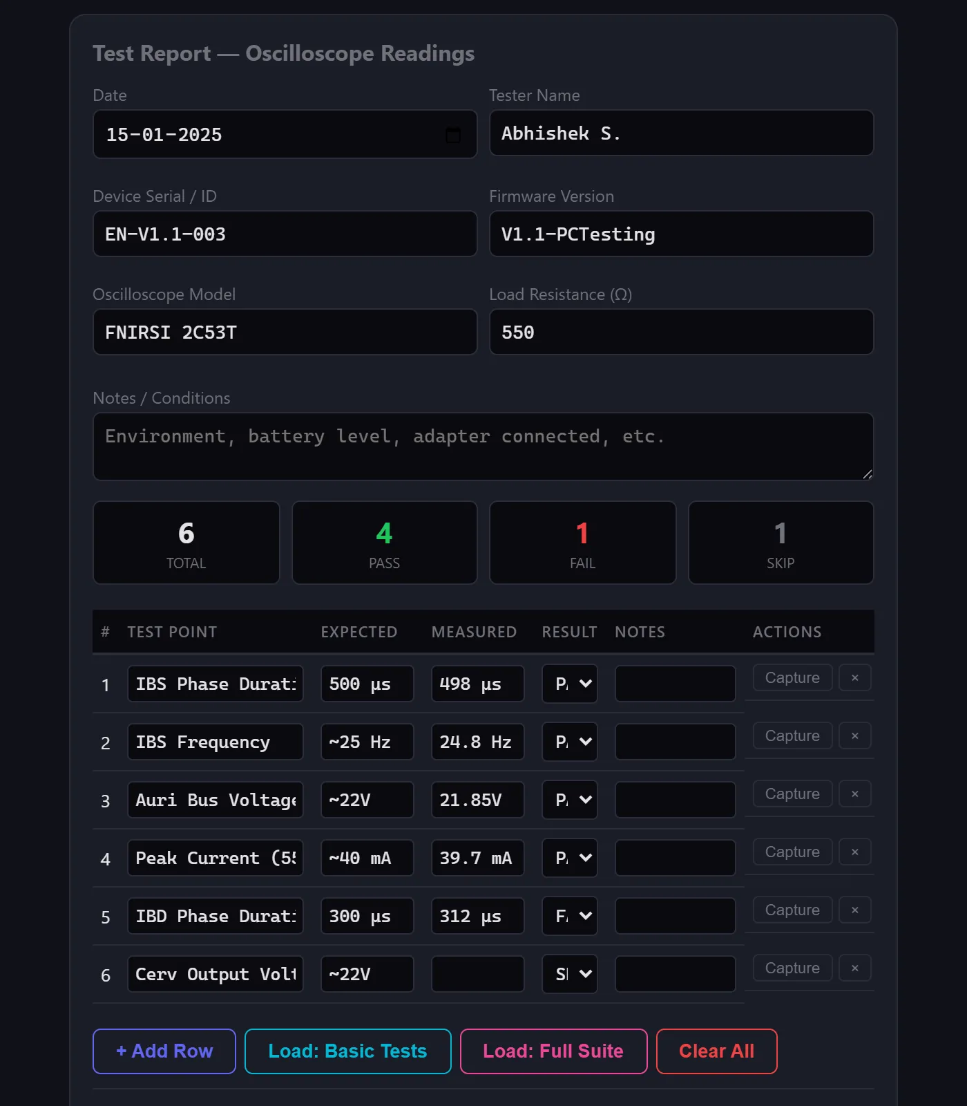
Test report with pre-loaded suites, live ADC capture, and MD/PDF export

Results

From five tools to one tab

The tool collapsed a fragmented workflow — flashing firmware, connecting BLE via nRF Connect, running RTT from CMD, setting up the scope from documentation, and writing results on paper — into a single browser tab. Testing became a flow state, not a context-switching exercise.

5 → 1

Tools consolidated into one interface

Faster cycles

Rapid test iterations without workflow fragmentation

Bugs caught

Reproducible states made bug reports actionable

Reflections

What I learned

Building this tool reinforced something I've believed for a while: the best developer tools don't add features — they remove friction. The Web Bluetooth API was the key enabler, letting me build a zero-install tool that connects directly to hardware from a browser. The biggest design challenge was serving two audiences — firmware engineers who want raw register access, and testers who just want to run treatments and log results. The dual-mode approach (Simple + Raw) solved this cleanly without compromising either experience.